Animated View

Version 1 (OLD)
Kamtrak gif

LAST UPDATED 12TH JULY 2010

Exhibition Videos


Here is a video of the Z1 test and initial thoughts are that it is slightly more sluggish than with the consumer JVC camera. This is in part due to the resolutions from each camera being different. The JVC is giving out 640X480 (a standard 4X3 resolution) whereas the Sony Z1 is giving a resolution of 720X576 (a standard 16X9 resolution). This means the X position doesnt quite catch up as fast as the Y position. This also results in more processing time being needed for the larger resolution to firstly process the incoming video signal and then add the recognition software. A way to help with this might be to ensure the digipot for the X coordinates has full resistance or 0V at a point which isnt at the edge of the screen and the same for no resistance or 24V.


Z1 Test 2

Photobucket
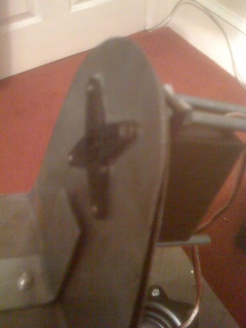
This photo shows how accurate the pan and tilt stop is. After moving around for a while I stop suddenly and the pan and tilt head stops central to my face. You can see in this photo of the fold out lcd monitor on the Z1 that the crosshairs aim between the eyes.


This video shows a limiting error when using the facial recognition in an uncontrolled lighting environment. The brightness of the light confuses the software and is possibly added to by the light having sharp corners. Further tests will be conducted in a controlled environment to simulate a studio.

Photobucket
Haar recognition error


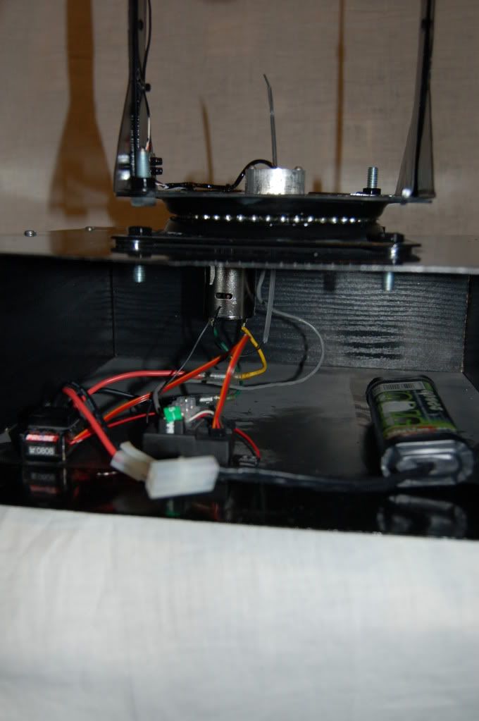
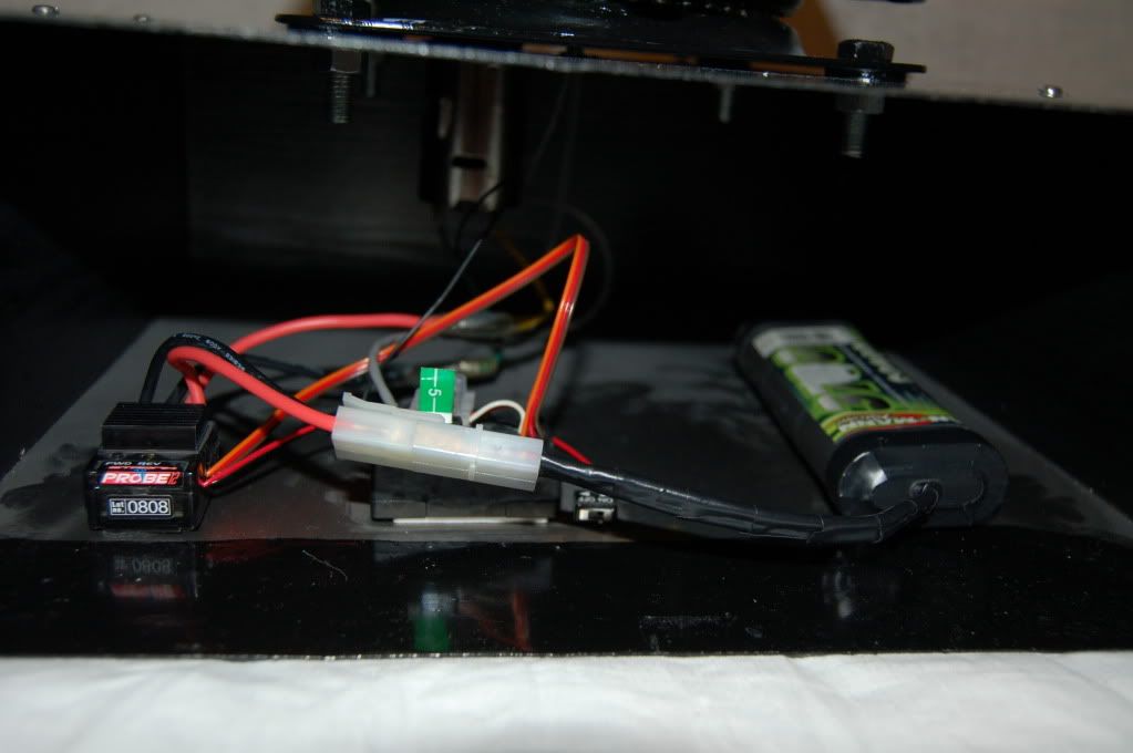
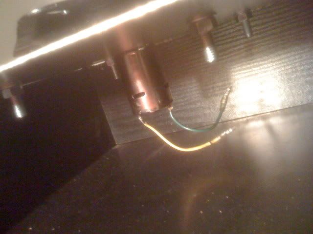
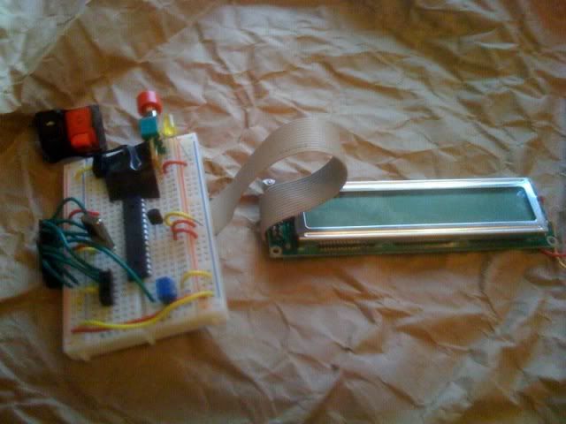
This is a video of the modified control box. There has also been some fuzzy logic coding implemented at this stage to give a pseudo random number. This gives the head a handheld look when viewing the camera output to make it more realistic and more human like.


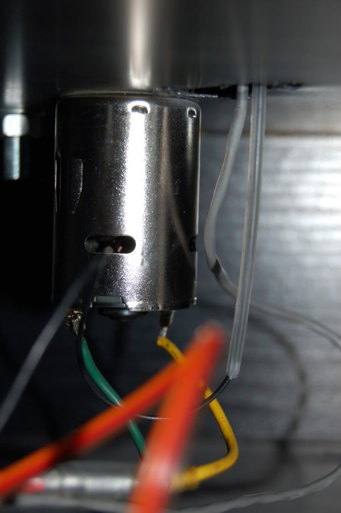
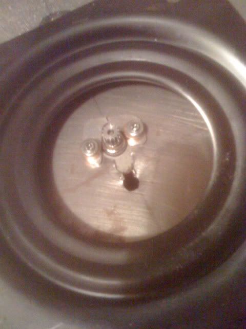
The data line is shared between the two digipots. This means the same data is being sent to both digital pots. The pots are switching in and out of this data at precise times via bringing the CS pin LOW and HIGH. This means the x coordinates are being handled by the x pot and the y coordinates are being handled by the y pot.


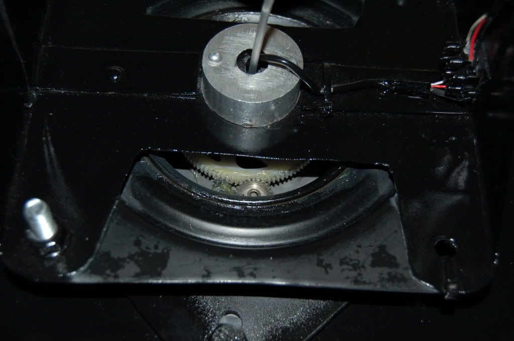
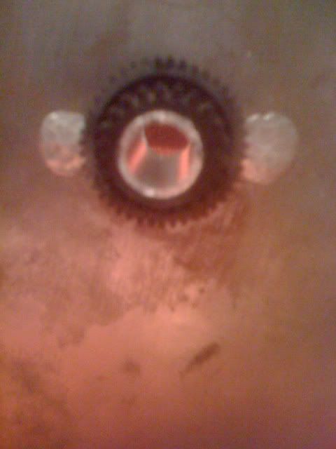
Here is the pan Motion working (sorry for dodgy camera) I will be connecting a Broadcast camera to the head in later tests


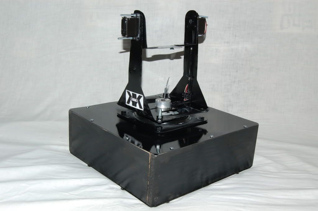
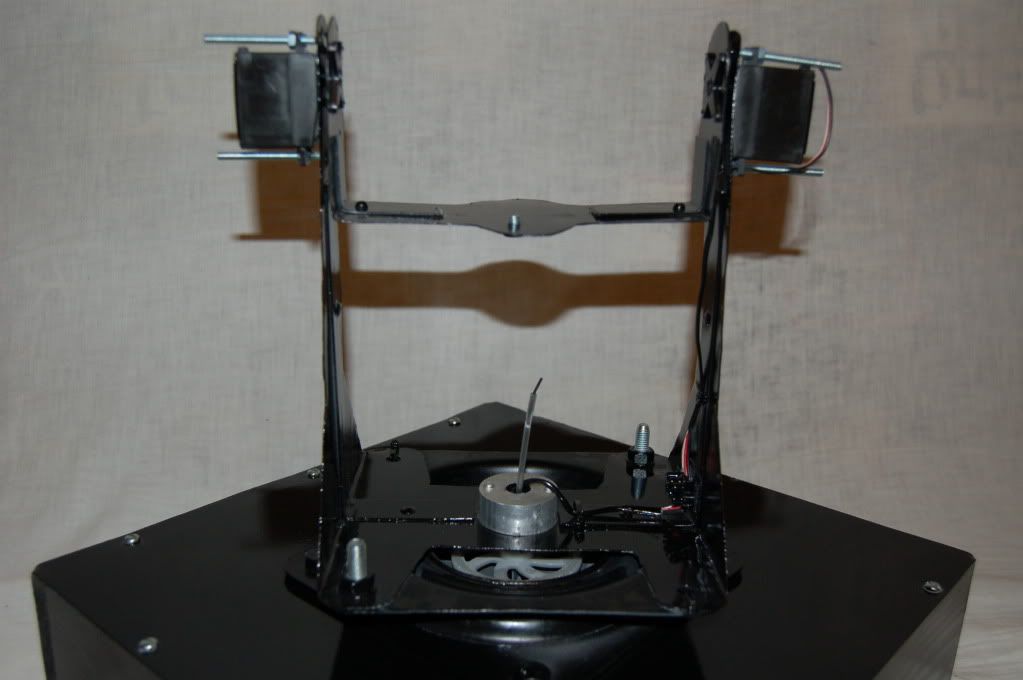
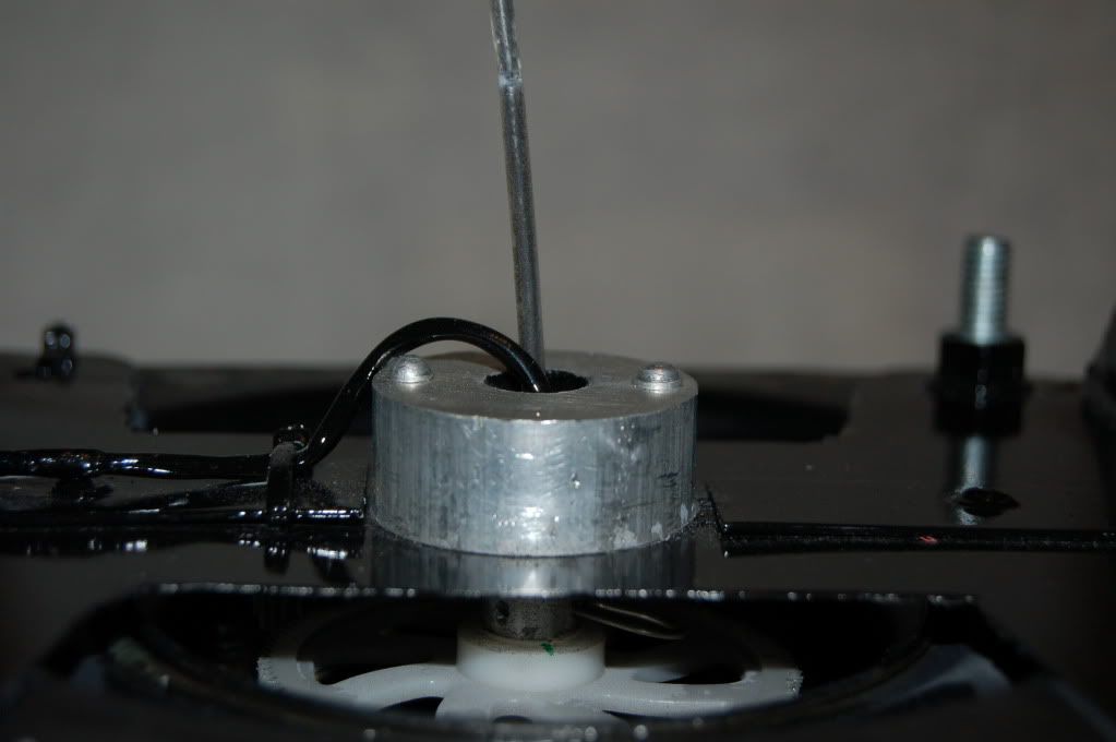
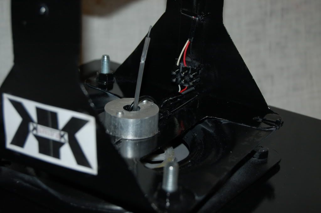
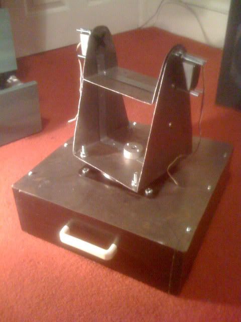
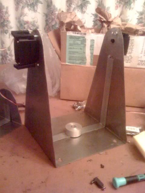
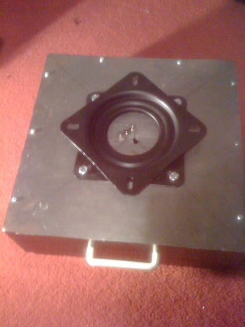
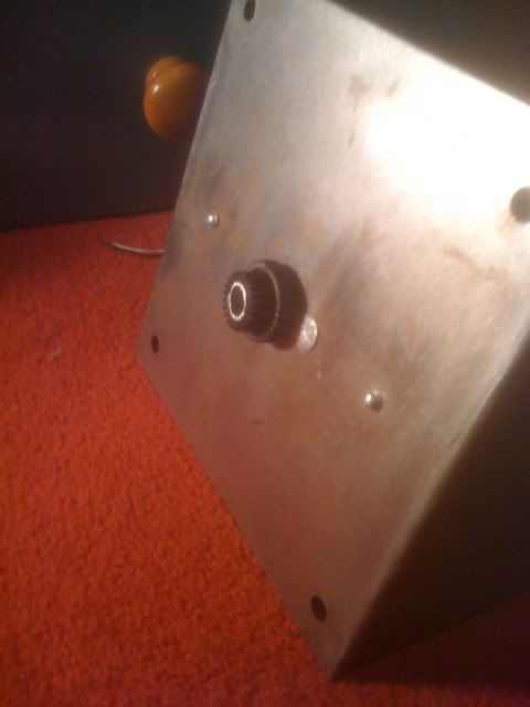
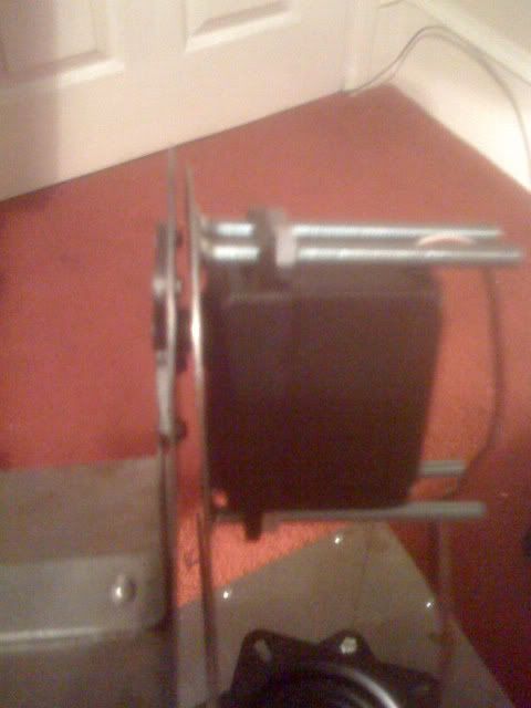
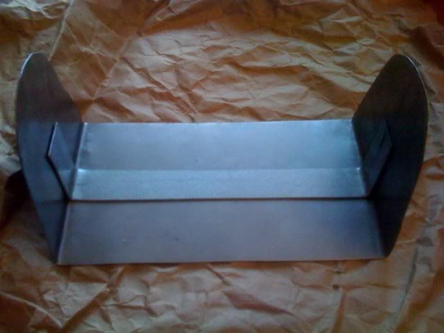
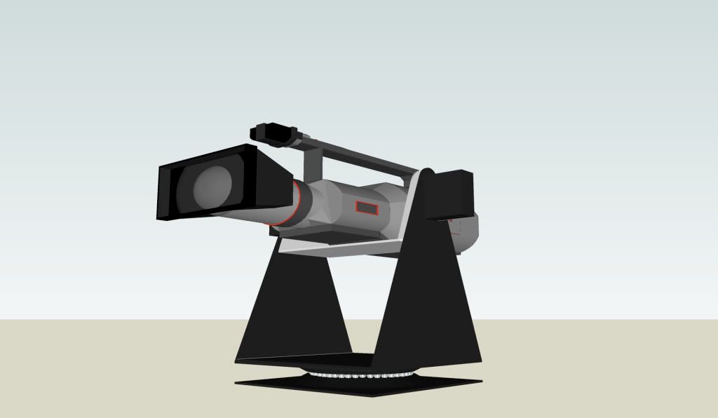
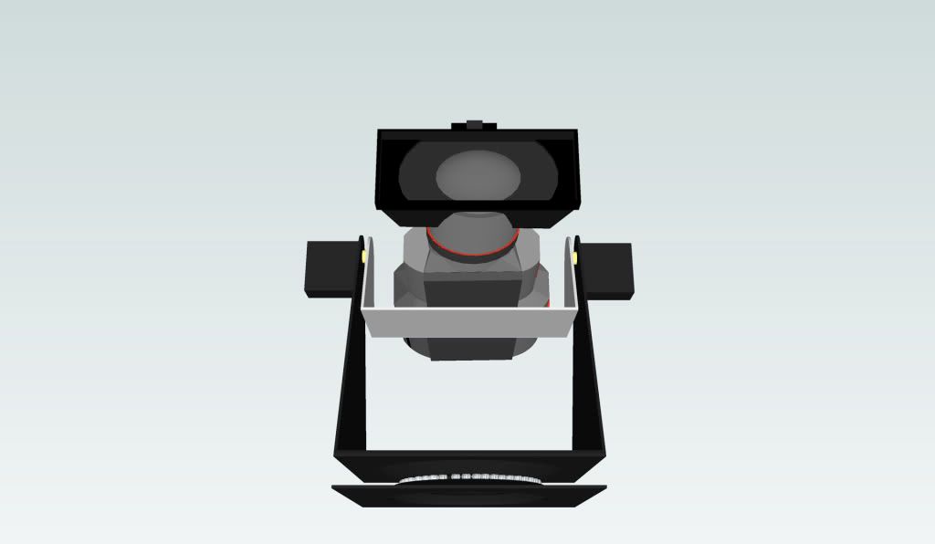
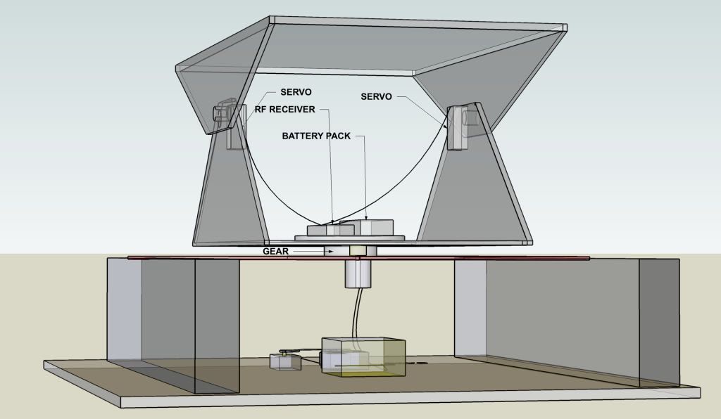
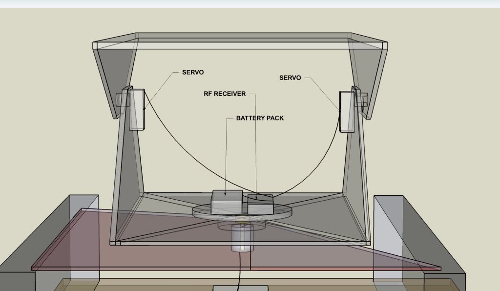
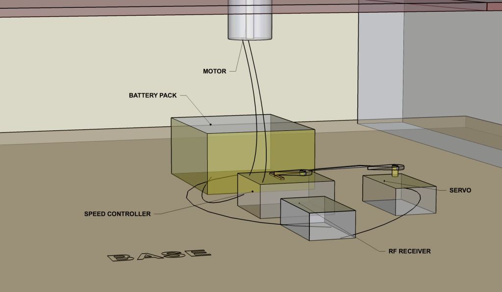
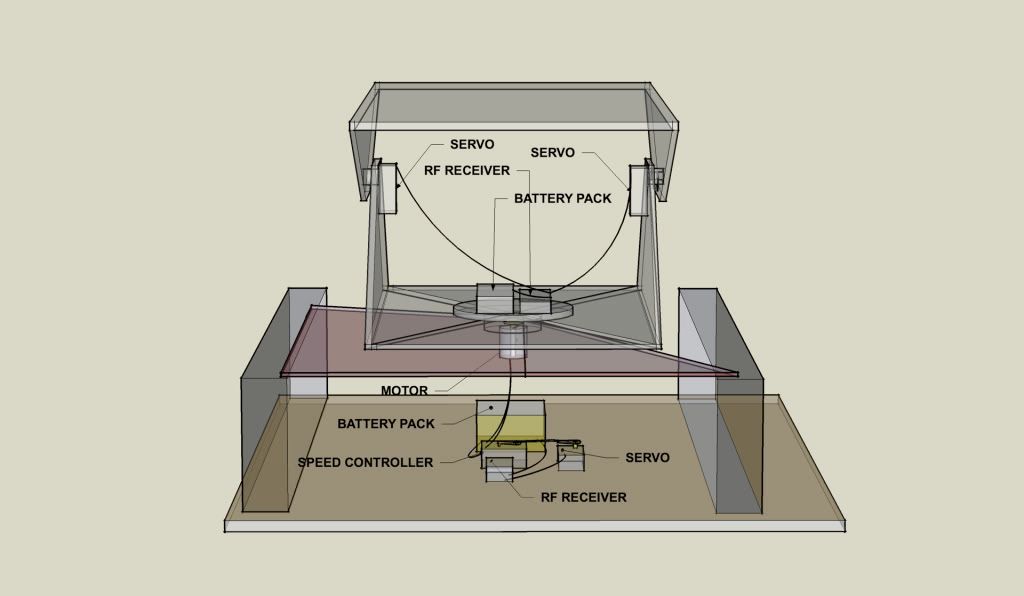
Here is the apparatus used


Test at 24v


Test at 5v

Last Updated 22nd JUNE 2010


  • The Testing for the pan motion has been completed. The digi pot is correctly resisting voltage and this is related to the data being sent to the arduino board.

    There were some initial problems with code which meant the map function which maps serial values to resistance values between 0 and 255. The serial values were only mapped from 130 to 530 this was changed to between 0 and 600 as when the data was outside of these values the resistance jumped quite significantly as the outside value was not included within the map function.

    This error meant that testing was slow and wiring was double and triple checked. I was surprised to see 5v coming out of the CLK pin but i guess this makes sense. All i needed to do was be brave and trust the wiring before cranking up the voltage to 24v from the desk power supply.

    Below are some photos of the test setup. The next part is to copy and tailor the code for the tilt function.

    Face tracking with voltage resisted

    arduino board

    digi pot

    desk psu


    A conversion using digital potentiometers has been completed for the pan motion of a larger rig. This rig can hold a broadcast camera easily. The control for the motors is achieved by sending an analogue voltage to the camera rig head.

    here is a picture of the MSOP digi pot on a breadboard adaptor taken from a microscope
    digipot


    These volts are 24v for one direction 0v for the opposing direction and 12v for stop.

    The conversion was completed today for the pan motion, so one digi pot has been used. Another will be used for the tilt motion.

    The digital pot works in a similiar way to physical pots like a standard volume pot. The digital pot receives a negative and postive voltage and a variably resisted output is achieved by controlling a wiper in software code. The output of the face tracking software takes the pixel coordinates for the position of a circle within the frame. This is then converted to Hex and sent over USB to an Arduino kit using the ATMEL ATmega 328 chip. A separate piece of code runs on this chip which converts the hex back to decimal coordinates which are mapped to a level of resistance.

    The digipot can take a maximum of 30v, 24v of which is divided between the two terminals A and B, or negative and positive, on the chip. Depending on where the circle is in the facetracking software, determines the level of resistance for the analogue voltage which should move the rig.


    Pan and tilt head
    This is the pan and tilt head which requires variable voltage from a 24v source. In this project I am using a digipot to resist the voltage in software


    Voltage test
    You can see when my face is situated in the left of frame, 4.77v is output from the digipot wiper.


    Voltage test
    When my face is situated in the right of frame, 1.1v is output from the digipot wiper. This proves the code is working for a low voltage. Now a 24v supply needs to be connected.


    setup
    Here is the setup consisting of a laptop running xcode and the facial tracking software, an arduino running different code, and a digipot being output to a voltmeter


    Servo amplifier
    This is the amplifier which drives the motors inside the pan and tilt head


    UPDATE The system is now operational with facial tracking working from a stationary camera. the Head mimics the subjects movements providing that the software recognises a face. The pixel mapping works and is mapped to the angle of the servos.

    The next step is to introduce a laplace transform which will dampen or smooth the voltage steps to give a smoother overall movement. This project will also be linked with a stereo pair of cameras for use with stereoscopic 3D applications.

    Microchip can now control a servo through the use of terminal and directional buttons from the laptop. This needs to be put into code form but shows that the communication between laptop and MCU is working.

  • Reducing the weight of the rig has been completed
  • Painting has been completed
  • Cabling in the servo is finished
  • Starting to work on controller electronics
  • Software is taking longer than expected - Have enlisted the help of a tutor
  • Camera rig now has an electronic speed controller (ESC) for the pan function. This has also stopped the over heating problem with the old mechanical speed controller.
  • The rig is now fully remote controlled.
  • New gearing mechanism made. Old mechanism was too small and couldnt take the load. The gear was also being stripped. New mechanism fits onto the end of the pipe with a split pin pushed through holes that were drilled in the pipe and gear. The gear now doesnt strip and grease has been applied
  • Having interference issues between the two channels. Trying to see if its the power from the transmitter maybe the batteries are low.

May 2009

  • Voltages measured for RF transmitter. These correspond to the type of signal sent to the RF Receiver which then outputs a voltage telling the servos what position to be in.
For the Transmitter these are:

2.2v for full left, 2.6v for middle and 2.9v for full right. The potentiometer has a constant voltage of 5.15v and the variable control voltages and also a ground.

For the Receiver the voltages are:

Data Cable (white) sends variable voltages of 0.28v for full left, 0.4v for middle, and 0.51v for full right. The power cables (+ and -) supply constant voltages to the servos. When the transmitter is off, no data voltage is generated.

  • The way in which the transmitter is controlled is by linking the microchip from nerdkits to the variable voltage output on the transmitter. The chip will generate a PWM (pulse width modulated) signal out to a capacitor which will charge and discharge with respect to the rate of PWM. This charge and discharge process will give the required voltages for the transmitter to produce its original signal when the potentiometer is altered manually.
  • The transmitter requires a minimum of 8.55v to function. So could possibly run off a 9v battery (probably not for very long).
  • The rig needs to be made lighter in weight as the motor is overheating. The process of cooling will not be enough as the load is probably too heavy for the motor anyway. This will be lightened by cutting out sections of the rig.

January until April 2009

  • Construction continues and design flaws are addressed (original Cable pipe could not be stuck to the pan part and so have had to rivet a milled out piece of aluminium) Rivots have been used for connecting a frame.
  • Found that servo's pivot range is more than adequate and so no further alterations are needed.
  • Will not dip coat but will spray the head at the end.
  • Had difficulties lining up the gear and the motor for the pan mechanism.
  • Found a much more reliable method of connecting the servos onto the pan and tilt parts.
  • Box was built to house electronics and form the base of the head.
  • Swivel plate seems to be rotating well.
  • Had difficulties fixing the gear to the pipe but after milling the gear to the correct diameter it slipped on easy. Etched teeth into the pipe to hold the gear.
  • All holes cut.
  • Will next have to wire in extension cables for servos and mount the rest of the electronics.

December 2008 - Construction of Hardware Begins

Decided to use design idea 2 as it is more lightweight than design idea 1 and it has addressed the issue of inertia by having a swing mechanism that pivots across the middle axis of the camera.

*Also a major design flaw was addressed. The way in which the central pipe with the gear connects to the centre point of the pan mechanism wouldn't have worked in the design. Have milled out some aluminium which will fix to the metal base and then will screw to the pipe.*

  • Nerdkit is programmed to be able to temperature sense near the MCU and send this information to the laptop. This proves that it is communicating with the laptop.
  • Nerdkit changed from 9v power being regulated to 5v - direct USB power without the need for a battery and voltage regulator.
  • Reset switch added.
  • On/Off switch added.

Parts Arrived

  • The parts have arrived and am very happy with them.
  • The swivel plate is just the right size, might be a bit heavy but will see
  • The Nerdkit works really well and a new programme has been installed onto it to show that it is easy to install. Next is the programming stage aswell as the building stage which will happen over Christmas.
  • Photos will be uploaded.
  • Have kept in contact with the guys from Nerdkits for any help needed, and they are interested to hear what i plan on doing with mine.
Monday 17th November 2008

  • Spoke to supplier of the swivel plate in China and got laughed at for only wanting to order one piece rather than between 500-999! She kindly decided to help a student in need and will be arranging the order soon.
  • Also found a USB device from www.nerdkits.com that can be used to programme a PIC they have specific projects that deal with radio controlling DC motors and regulating the speed via PWM (pulse width modulation).

KamtraK research begins

Research notes.

WEEK 1

Monday 6 October 2008

  • Briefing on engineering project. Ideas proposed and initial idea completely changed because it would be too hard.

Thursday 9 October 2008

  • Brain storming and class discussion on ideas. Began to really think about what I could do.

Friday 10 October 2008

  • Ideas and research into some ideas. I liked the idea of using object recognition software and motion tracking. Google motion tracking found some videos on youtube of programmers using it.


WEEK 2

Monday 13 October 2008

  • More research. Looked at b-hague website but videos show that the movement of the camera isn’t designed for fast pan and tilt actions. Could uprate the servos inside. Have emailed them to ask. Feedback received on 24th October.
http://www.b-hague.co.uk/pan__tilt_power_head.htm

WEEK 3

Thursday 23 October 2008

  • Looked at cctv heads from denmark and emailed
http://www.2bsecurity.com/00085/ to ask how fast these heads can move.

Friday 24 October 2008

  • Found an American website that deals in robotics that make fast pan and tilt heads but these are for small cameras. Have emailed this company about providing the same speed of movement but for a handheld camera weighing 2.7kg
http://www.superdroidrobots.com/shop/default.asp
  • Feedback on project proposal received. Need to rewrite aims and objectives and then write a Gantt chart to follow these aims.

  • Spoken to contact at hiflyer productions who referred me to an engineer will speak to him soon.

  • Spoken to a friend and have arranged for track testing with go-karts to find out the speed of pan and tilt needed. Will then test product here aswell.

  • Received feedback from B-Hague original message sent on 13th October copy of email below

“Andy,
The power head units can only be supplied at the speeds that are listed on the website but we do have a USB controller for them which can be found further down the power heads page.
Kind Regards,
Mark Scotton
B-Hague & Co Ltd
45 Mile End Road
Colwick
Nottingham
NG4 2DW
www.b-hague.co.uk
www.cameragrip.co.uk
mark@b-hague.co.uk
BUY OUR VIDEOS PRODUCTS ONLINE NOW AT www.cameragrip.co.uk
Phone : +44 (0) 115 987 0031
Fax : +44 (0) 115 987 2900
-----Original Message-----
From: Andy Buckland [mailto:awbuckland@yahoo.co.uk]
Sent: 24 October 2008 10:30
To: info@b-hague.co.uk
Subject: Hague pan and tilt power heads
Hello,
I'm an engineering student studying broadcast engineering. For my final year project i need to find a pan and tilt head and that is how i came across your website. I really like these devices but having watched the videos i found that the pan and tilt action was too slow for the application i need to use it for.
Is there any way the servo system can be sped up or uprated to achieve faster pan and tilt actions?
Also is there anyway that instead of the control being plugged in can the head be plugged into a laptop for control?
Any help would be much appreciated
Andy Buckland
07763 694 876”


Thursday 30th October 2008

  • Reading tutorial for C++ http://www.cplusplus.com/doc/tutorial/

Still confused about some aspects of structure, functions and general language.


Thursday 6th November 2008

  • Found a project similar to mine that was done over a year ago. Posted a reply in a forum to the person who did it might not hear anything back as the forum is old.
http://www.electro-tech-online.com/forumdisplay.php?f=15

  • Found a website from the forum that deals with servo systems
http://picprojects.org.uk/projects/zcode/index.htm

  • Found a video on youtube of a turret that moves really fast and is a good idea for design of the rig
http://uk.youtube.com/watch?v=Kg1hSx-_iHs&feature=related

* Tutorial with Lecturer, came up with some action points.

Look at reference for image data processing on Moodle project brief.

Action points block diagram of hardware DONE

Clear idea of mechanical – have it ready DONE
Market research


Sunday 9th November 2008

  • Scavenged servos, motors, RF receivers, controls, and other parts from old model cars to use with project.

Monday 10th November 2008
and
Tuesday 11th November 2008

  • Drew up plans for basic ideas with notations and multiple views. Have designed mechanical parts of which there are three main parts to the product. Have looked at materials and aesthetics as well as weight saving issues.

Thursday 13th November 2008

  • Looked at servos taken from model cars. Found that they can be modified to turn fully 360 degrees if needs be. They currently turn at about 90 degrees. But they can do 180. The controller will need to be modified.
  • Also made a logo in photoshop.
  • Tested servos with controls to make sure they still worked SUCCESS!

* Tutorial with Lecturer

Action points

Set Gantt chart to display in weeks rather than days DONE

Look at Blog writing DONE

Make a different log of links and references as a crossover document to tie in with log


Saturday 15th November 2008

  • Looked at swivel plates for connecting base to middle pan part.
  • Went to B&Q, Homebase, and Focus but couldn’t find anything.
  • Found the one im looking for but have had to email manufacturer for details of where I can buy this product. Product is shown in parts section.

http://heshengwj.en.alibaba.com/product/200065504/201583324/bar_chair_swivel.html